ICGOO在线商城 > BFR 460L3 E6327
 Datasheet下载
- 型号: BFR 460L3 E6327
- 制造商: Infineon
- 库位|库存: xxxx|xxxx
- 要求:
| 数量阶梯 | 香港交货 | 国内含税 |
| +xxxx | $xxxx | ¥xxxx |
查看当月历史价格
查看今年历史价格
BFR 460L3 E6327产品简介:
ICGOO电子元器件商城为您提供BFR 460L3 E6327由Infineon设计生产,在icgoo商城现货销售,并且可以通过原厂、代理商等渠道进行代购。 提供BFR 460L3 E6327价格参考以及InfineonBFR 460L3 E6327封装/规格参数等产品信息。 你可以下载BFR 460L3 E6327参考资料、Datasheet数据手册功能说明书, 资料中有BFR 460L3 E6327详细功能的应用电路图电压和使用方法及教程。
| 参数 | 数值 |
| 产品目录 | |
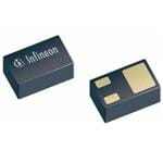
| 描述 | TRANS RF NPN 5.8V 50MA 3TSLP |
| 产品分类 | RF 晶体管 (BJT) |
| 品牌 | Infineon Technologies |
| 数据手册 | http://www.infineon.com/dgdl/bfr460l3.pdf?folderId=db3a30431400ef68011425b2dfaf05c6&fileId=db3a30431400ef680114271ab45806d6 |
| 产品图片 |
|
| 产品型号 | BFR 460L3 E6327 |
| PCN封装 | |
| rohs | 无铅 / 符合限制有害物质指令(RoHS)规范要求 |
| 产品系列 | - |
| 不同 Ic、Vce 时的DC电流增益(hFE)(最小值) | 90 @ 20mA,3V |
| 供应商器件封装 | PG-TSLP-3 |
| 其它名称 | BFR 460L3 E6327CT |
| 功率-最大值 | 200mW |
| 包装 | 剪切带 (CT) |
| 噪声系数(dB,不同f时的典型值) | 1.1dB ~ 1.35dB @ 1.8GHz ~ 3GHz |
| 增益 | 16dB |
| 安装类型 | 表面贴装 |
| 封装/外壳 | SC-101,SOT-883 |
| 工具箱 | /product-detail/zh/KIT%20RF%20TRANS.%202/KITRFTRANS.2IN-ND/2025016 |
| 晶体管类型 | NPN |
| 标准包装 | 1 |
| 电压-集射极击穿(最大值) | 5.8V |
| 电流-集电极(Ic)(最大值) | 50mA |
| 频率-跃迁 | 22GHz |


- 商务部:美国ITC正式对集成电路等产品启动337调查
- 曝三星4nm工艺存在良率问题 高通将骁龙8 Gen1或转产台积电
- 太阳诱电将投资9.5亿元在常州建新厂生产MLCC 预计2023年完工
- 英特尔发布欧洲新工厂建设计划 深化IDM 2.0 战略
- 台积电先进制程称霸业界 有大客户加持明年业绩稳了
- 达到5530亿美元!SIA预计今年全球半导体销售额将创下新高
- 英特尔拟将自动驾驶子公司Mobileye上市 估值或超500亿美元
- 三星加码芯片和SET,合并消费电子和移动部门,撤换高东真等 CEO
- 三星电子宣布重大人事变动 还合并消费电子和移动部门
- 海关总署:前11个月进口集成电路产品价值2.52万亿元 增长14.8%


PDF Datasheet 数据手册内容提取
BFR460L3 Low Noise Silicon Bipolar RF Transistor • For low voltage / low current applications • Ideal for VCO modules and low noise amplifiers • Low noise figure: 1.1 dB at 1.8 GHz • Excellent ESD performance typical value 1500V (HBM) • High f of 22 GHz T • Pb-free (RoHS compliant) and halogen-free thin small leadless package • Qualification report according to AEC-Q101 available ESD (Electrostatic discharge) sensitive device, observe handling precaution! Type Marking Pin Configuration Package BFR460L3 AB 1 = B 2 = E 3 = C TSLP-3-1 Maximum Ratings at T = 25 °C, unless otherwise specified A Parameter Symbol Value Unit Collector-emitter voltage V V CEO T = 25 °C 4.5 A T = -55 °C 4.2 A Collector-emitter voltage V 15 CES Collector-base voltage V 15 CBO Emitter-base voltage V 1.5 EBO Collector current I 50 mA C Base current I 5 B Total power dissipation1) P 200 mW tot T ≤ 108°C S Junction temperature T 150 °C J Storage temperature T -55 ... 150 Stg 1T is measured on the collector lead at the soldering point to the pcb S 1 2013-09-13
BFR460L3 Thermal Resistance Parameter Symbol Value Unit Junction - soldering point1) R 210 K/W thJS Electrical Characteristics at T = 25 °C, unless otherwise specified A Parameter Symbol Values Unit min. typ. max. DC Characteristics Collector-emitter breakdown voltage V 4.5 5.8 - V (BR)CEO I = 1 mA, I = 0 C B Collector-emitter cutoff current I - - 10 µA CES V = 15 V, V = 0 CE BE Collector-base cutoff current I - - 100 nA CBO V = 5 V, I = 0 CB E Emitter-base cutoff current I - - 1 µA EBO V = 0,5 V, I = 0 EB C DC current gain h 90 120 160 - FE I = 20 mA, V = 3 V, pulse measured C CE 1For the definition of R please refer to Application Note AN077 (Thermal Resistance Calculation) thJS 2 2013-09-13
BFR460L3 Electrical Characteristics at T = 25 °C, unless otherwise specified A Parameter Symbol Values Unit min. typ. max. AC Characteristics (verified by random sampling) Transition frequency f 16 22 - GHz T I = 30 mA, V = 3 V, f = 1 GHz C CE Collector-base capacitance C - 0.28 0.45 pF cb V = 3 V, f = 1 MHz, V = 0 , CB BE emitter grounded Collector emitter capacitance C - 0.14 - ce V = 3 V, f = 1 MHz, V = 0 , CE BE base grounded Emitter-base capacitance C - 0.55 - eb V = 0.5 V, f = 1 MHz, V = 0 , EB CB collector grounded Minimum noise figure NF dB min I = 5 mA, V = 3 V, Z = Z , C CE S Sopt f = 1.8 GHz - 1.1 - f = 3 GHz - 1.35 - Power gain, maximum stable1) G - 16.0 - dB ms I = 20 mA, V = 3 V, Z = Z , C CE S Sopt Z = Z , f = 1.8 GHz L Lopt Power gain, maximum available1) G - 11 - dB ma I = 20 mA, V = 3 V, Z = Z , C CE S Sopt ZL = ZLopt , f = 3 GHz Transducer gain |S |2 dB 21e I = 20 mA, V = 3 V, Z = Z = 50Ω, C CE S L f = 1,8 GHz - 14 - f = 3 GHz - 10 - Third order intercept point at output2) IP3 - 27 - dBm V = 3 V, I = 20 mA, f = 1.8 GHz CE C 1dB compression point at output P - 11.5 - -1dB I = 20 mA, V = 3 V, f = 1.8 GHz C CE 1G = |S / S | (k-(k²-1)1/2), G = S / S ma 21 12 ms 21 12 2IP3 value depends on termination of all intermodulation frequency components. Termination used for this measurement is 50Ω from 0.1 MHz to 6 GHz 3 2013-09-13
BFR460L3 Total power dissipation P = ƒ(T ) Collector-base capacitance C = ƒ(V ) tot S cb CB f = 1MHz 240 0.8 pF mW 0.6 160 Ptot cb 0.5 C 120 0.4 0.3 80 0.2 40 0.1 0 0 0 15 30 45 60 75 90 105 120 °C 150 0 2 4 6 8 10 V 14 TS VCB Transition frequency f = ƒ(I ) Power gain G , G , |S |2 = ƒ (f) T C ma ms 21 f = 1 GHz V = 3 V, I = 20 mA CE C V = parameter in V CE 26 50 GHz dB 2 to 4V 22 1V 40 20 35 18 30 T 16 G f 14 25 Gms 12 20 10 15 |S21|² 8 Gma 10 6 5 4 2 0 0 5 10 15 20 25 30 35 mA 45 0 1 2 3 4 GHz 6 IC f 4 2013-09-13
BFR460L3 Power gain G , G = ƒ (I ) Power gain G , G = ƒ (V ) ma ms C ma ms CE V = 3V I = 20 mA CE C f = parameter in GHz f = parameter in GHz 24 24 dB 0.9 dB 0.9 20 20 18 18 1.8 16 1.8 16 G G 14 2.4 14 2.4 12 3 12 3 10 4 5 8 10 4 6 6 8 5 4 6 6 2 4 0 0 5 10 15 20 25 30 mA 40 0.5 1 1.5 2 2.5 3 3.5 V 4.5 IC VCE 5 2013-09-13
BFR460L3 SPICE GP Model For the SPICE Gummel Poon (GP) model as well as for the S-parameters (including noise parameters) please refer to our internet website www.infineon.com/rf.models. Please consult our website and download the latest versions before actually starting your design. You find the BFR460L3 SPICE GP model in the internet in MWO- and ADS-format, which you can import into these circuit simulation tools very quickly and conveniently. The model already contains the package parasitics and is ready to use for DC and high frequency simulations. The terminals of the model circuit correspond to the pin configuration of the device. The model parameters have been extracted and verified up to 6 GHz using typical devices. The BFR460L3 SPICE GP model reflects the typical DC- and RF-performance within the limitations which are given by the SPICE GP model itself. Besides the DC characteristics all S-parameters in magnitude and phase, as well as noise figure (including optimum source impedance, equivalent noise resistance and flicker noise) and intermodulation have been extracted. 6 2013-09-13
Package TSLP-3-1 BFR460L3 7 2013-09-13
BFR460L3 Edition 2009-11-16 Published by Infineon Technologies AG 81726 Munich, Germany 2009 Infineon Technologies AG All Rights Reserved. Legal Disclaimer The information given in this document shall in no event be regarded as a guarantee of conditions or characteristics. With respect to any examples or hints given herein, any typical values stated herein and/or any information regarding the application of the device, Infineon Technologies hereby disclaims any and all warranties and liabilities of any kind, including without limitation, warranties of non-infringement of intellectual property rights of any third party. Information For further information on technology, delivery terms and conditions and prices, please contact the nearest Infineon Technologies Office (<www.infineon.com>). Warnings Due to technical requirements, components may contain dangerous substances. For information on the types in question, please contact the nearest Infineon Technologies Office. Infineon Technologies components may be used in life-support devices or systems only with the express written approval of Infineon Technologies, if a failure of such components can reasonably be expected to cause the failure of that life-support device or system or to affect the safety or effectiveness of that device or system. Life support devices or systems are intended to be implanted in the human body or to support and/or maintain and sustain and/or protect human life. If they fail, it is reasonable to assume that the health of the user or other persons may be endangered. 8 2013-09-13
Mouser Electronics Authorized Distributor Click to View Pricing, Inventory, Delivery & Lifecycle Information: I nfineon: BFR 460L3 E6327